Monday, August 8, 2022

Godrej Single Door Refrigerator Wiring Diagram

Godrej refrigerator/fridge service, repairing, overhauling & maintenance. Diagrams for wire wellread me, godrej refrigerator compressor wiring diagram, godrej gsc 18 fga 5 wog service manual pdf download, wiring diagram for refrigerator godrej double door, manual refrigerator diagnostic service manual, refrigerator circuit diagram pdf wordpress com, pictures refrigerator 2 / 4


Westinghouse Mrt12crey1 Refrigerator Wiring Diagram

Godrej refrigerator compressor relay pack of 1 piece.

Godrej single door refrigerator wiring diagram. Refrigerator not cooling repair guide. Otherwise, the arrangement won't work as it should be. Mr services specialises in servicing & repairing frost free & rf cooled godrej refrigerators of following capacities:

Refrigerator is provided with a door push switch, which closes on opening of refrigerator and puts the lamp on. Need complete ebook godrej refrigerator wiring diagram please fill out registration form to access in our databases summary pictures refrigerator compressor wiring diagram godrej fridge whirlpool for Godrej bc type 19 5 wp refrigerator relay amazon in home.

Refrigerator not cooling repair guide. It will also consist of provides you could need to full simple assignments. Refrigerator compressor wiring diagram wiring schematic diagram results page 59 about digital security system searching solar balloon bovine aerospace 523d6 lg washing machine motor wiring diagram wiring resources frigidaire 20 4 cu ft top freezer refrigerator black stainless double door fridge timer wiring.

Godrej bc type 19 5 wp refrigerator relay amazon in home. Identify problem of double door refrigerator and solve godrej pentacool refrigerator manual refrigerator is good but after buying 1 month is problem due to wrong guidelines. Godrej refrigerator wiring diagram wiring diagram for refrigerator fileschematic wiring diagram of domestic refrigerator photo.

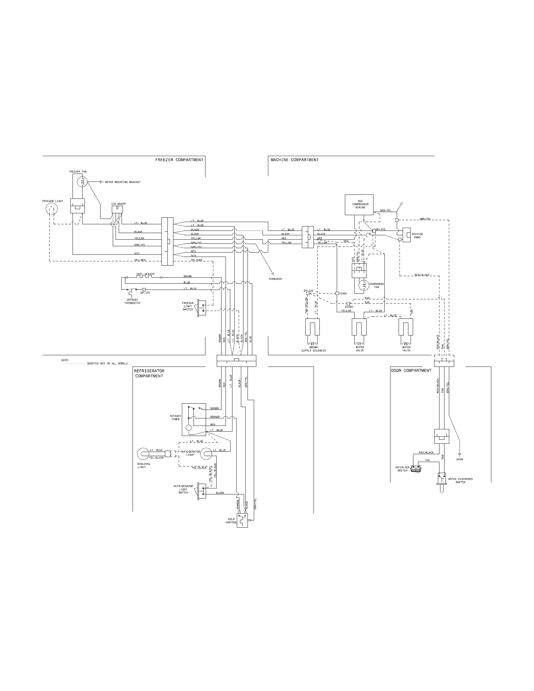
How to refrigerator single door wiring in hindi single door refrigerator wiring diagram Each component should be set and linked to different parts in specific way. Most refrigerators come with a warranty period, which ensures that you don't have to do any repair work on them spending money out of your own pocket until this period lapses.

Refrigerator compressor wiring diagram 230v wiring diagram. Freeze wiring diagram best refrigerator models in godrej double door refrigerator not cooling ! Godrej refrigerators were conferred the national energy conservation award 2009 by the government of india.

Godrej & boyce received the leader in energy efficiency & sustainability award. Refrigerator compressor wiring diagram 230v wiring diagram. How to refrigerator single door wiring in hindi single door refrigerator wiring diagram

Electrical circuit of a refrigerator is shown in fig. Wiring diagram for refrigerator godrej double door april 10th, 2019. If not, the arrangement will not function as it should be.

2 3 scope of the compressors. Godrej refrigerator compressor relay pack of 1 piece. So, if you can find a godrej refrigerator single door, then don't shy away from it.

Godrej single door, double door refrigerator models of 165, 195, 245, 330 litres to 345 litres. Godrej bhawan got the leed gold certification by the us building council, the first such building in mumbai. Each part should be placed and linked to other parts in particular way.


Lg Refrigerator Compressor Wiring Diagram


Icon Refrigerator Vector Home Depot LG Refrigerator


Wiring Diagram Camper Refrigerator Dm2652


Simple Wiring Diagram Of Fridge Wiring Sample


Refrigerator Compressor Schematic Complete Wiring Schemas


Simple Wiring Diagram Of Fridge Wiring Sample


Westinghouse Wiring Diagram Complete Wiring Schemas


Simple Wiring Diagram Of Fridge Wiring Sample


Godrej Refrigerator Compressor Wiring Diagram MORPHINE


MAYTAG REFRIGERATOR WIRING DIAGRAM WIRING DIAGRAM


Samsung Refrigerator Wiring Diagram Complete Wiring Schemas


Sanyo Refrigerator Wiring Diagram Wiring Diagram


Videocon Double Door Refrigerator Wiring Diagram Wiring


Refrigerator Compressor Wiring Kenmore Elite Refrigerator


72 Nova Wiring Diagram MORPHINEANDDRUGS


Godrej Double Door Refrigerator Wiring Diagram Double


Godrej Refrigerator Thermostat Price


Simple Wiring Diagram Of Fridge Wiring Sample


Videocon Refrigerator Wiring Diagram Complete Wiring Schemas

Solar Lights Wiring Diagrams

Presented here is the circuit of a solar light that is bright enough to illuminate a garden while not requiring any wiring to the grid supply and thus lowering the electricity bill. Working of solar garden lights circuit:


Schematic wiring diagram of the solar streetlight

With four panels we clearly have enough of them to arrange them using a combination of series and parallel wiring.

Solar lights wiring diagrams. One is charging and the other one is to control the leds. In this solar panel diagram wiring application we will also explain in detail. Individual silicon cells produce only around 0 6v and so enough of them have to be connected together in.

Boat solar panel wiring diagram. The following wiring diagram shows that the two 12v 10a 120w solar panels connected in parallel will charge the two 12v 100ah parallel connected batteries as well as power up the ac load through batteries and inverter during the day in normal sunshine. The wiring diagrams for combiner boxes will usually be accompanied by illustrations detailing the mounting, electrical components, and the box's input and output wiring points, as illustrated below.

The solar garden light circuit will consist of two parts. The above circuit can be classified into two sections charging section (from panel to battery) and lighting section (from battery to led's). A four panel solar system wired in series & parallel the next solar power wiring diagram (arrangement) we'll look at consists of four solar panels and a battery bank with four batteries in it.

There is a switch in the positive wire between the solar panel and the controller. Now this lamp load at the output of t1 energises. With the incidence of sunlight or other light sources on all solar panels, a voltage appears at the output terminals of the solar panel turning it into a source of electricity.

Www.onsemi.com 24 number of leds required 175 w metal halide 7,700 66 44 141 130 90. Solar panel forms the backbone of the above circuit. Solar panel wiring diagram #3:

The complete circuit diagram is explained as two parts, the first part is given below. Hopefully those looking for practical information on electrical circuits and wiring led components found this guide first. Solar garden light circuit diagram.

To avoid a shock hazard make sure the solar panel is covered with an opaque (dark) material such as paper or cloth during the installation. Fairy flashing led lights christmas light teardown the tech circuit inside 2 wire strings da share outdoor garden solar how to fix broken on make powered string converting ordinary rice bulb do with 3 wires work diagram schematic fairy flashing led lights christmas led light teardown the tech blog led christmas lights circuit circuit inside read more. Solar panel wiring diagram pdf what s wiring diagram.

Build a solar garden light wiring diagram schematic. It's likely though, you've already read the wikipedia page about series and parallel circuits here, maybe a few other google search results on the subject and are still unclear or wanting more specific information as it pertains to leds. Most decent 12v nominal panels will output a voltage of around 16 0 to 19 0 volts.

If you don't get a wiring diagram with your combiner box, they can usually be found on the manufacturer's website documentation downloads or technical support. Led solar lights circuit schematic here ic1 is wired as a medium current inverting line driver, switched by an encapsulated light detector (10mm ldr). This solar garden lights circuit will help you to build a simple solar powered garden led lights.


Sola Transformer Wiring Diagram Collection


Solar Street Light Connection Diagram


Solar Street Light Connection Diagram


How To Wire Two 24V Solar Panels in Parallel with Two, 12V


Automatic 40 Watt LED Solar Street Light Circuit Project


Solarpowered Automatic Lighting Schematic Circuit Diagram


Electronic Solar Street Night Lights Diagrams 230 V 50hz


Solar electrical diagram critique The Build Van life


Solar garden light DIY MadeInFck


Solar Circuits Motorcycle LED Turn Signal Wiring Harness


Solar Street Lamp with Outdoor Roadway Lighting System


Solar Panels Wiring Diagram Installation Download


How to Install solar Panels Wiring Diagram Collection


Solar lighting diagram Caravan Solar Panel Kits & Chargers


How to Make Solar Powered String Lights


Automatic Solar Garden Lights with LEDs


Outdoor Garden LED Solar Light Circuit


Solar Panels Wiring Diagram Installation Download


Solar LED circuit diagram

Sunday, August 7, 2022

Review Of Hydraulic Flow Control Valve Working Principle Ideas

Review Of Hydraulic Flow Control Valve Working Principle Ideas. The flow rate is also responsible for determining the rate of energy transfer at any specific level of pressure. For example, they benefit situations where it is necessary to maintain a constant speed of operation of a hydraulic cylinder regardless of the magnitude of.

GATE VALVE WORKING PRINCIPLE Mechanical engineering concepts and
GATE VALVE WORKING PRINCIPLE Mechanical engineering concepts and from www.hkdivedi.com

The primary purpose of the flow control valve is to regulate the flow rate of fluids to various components in a hydraulic circuit. There are many types of hydraulic control valves available, which are further divided into sub types. The working principle of control valve is opening or closing internal passages in order to regulate the flow of a liquid or gas.

What Can I Do For You?


When the valve is wide open, the valve ends differential pressure is 0.1 mpa, fluid density is 1 g/cm3, each hour flow diameter valve flow number, called flow capacity, also called flow coefficient to cv said, the unit is t/h, liquid cv. Hydraulic valves are used for different specifications and at different places in the hydraulic machine to control the flow, direction, and pressure of liquid. In hydraulics, flow control valves are used to control the volume of oil supplied to different parts within a hydraulic system.

It Directly Helps In Controlling Any Flow Rate And In Regulating Other Vital Processes Or Their Quantities Such As Temperature, Liquid Level, Liquid Flow, And Pressure.


Do not install this flow control valve when the user is away from the heat source more than 80% of the heating radius. There are many types of hydraulic control valves available, which are further divided into sub types. Plain structure, simple operation, and a wide range of adjustments are the advantages of flow control valves.

Full Flow Hydraulic Filter Will Also Be Associated With A Bypass Relief Valve.


An actuator is a pneumatic hydraulic, used to predict flow rate. One does not being changed with the pressure of the inlet and outlet, is called fixed throttle port, also called flow sensor, referred to as throttle valve. When the spool moves to the right for a certain interval, the pressure oil input by the hydraulic pump wins from the p port of the valve through the a port to the right cavity of the hydraulic cylinder, the oil in the right cavity of the hydraulic cylinder.

This Way, The Speed Of A Cyli.


Control valves adjust internal openings in response to instructions from the controller. Flow capacity cv is to choose one of the main parameters of control valve, regulating valve's flow capacity defined as: The valves which are mainly used to regulate the flow of fluid in hydraulic circuits are known as "flow control valves".

In Automatic Control Terminology, A.


The principle of direct acting valve. China hydraulic flow control valve working principle manufacture, visit here to find the hydraulic flow control valve working principle that you are searching for. Control valves are valves used to control conditions such as flow, pressure, temperature, and liquid level by fully or partially opening or closing in response to signals received from controllers that compare a "setpoint" to a "process variable" whose value is provided by sensors that monitor changes in.

Sonoff Th16 Wiring Diagram

Rj11 Socket Wiring Diagram Australia, How to punch down an RJ11 Telephone Jack, 6.36 MB, 04:38, 387,634, CableSupply.com, 2009-08-05T00:16:...