Tuesday, September 27, 2022

1 2 Hp Electric Motor Wiring Diagram

1 2 Hp Electric Motor Wiring Diagram

Rj11 Socket Wiring Diagram Australia, How to punch down an RJ11 Telephone Jack, 6.36 MB, 04:38, 387,634, CableSupply.com, 2009-08-05T00:16:07.000000Z, 19, Rj11 Socket Wiring Diagram Australia | Computacion, Redes de computadoras, Computadoras, www.pinterest.com.mx, 728 x 783, jpeg, rj11 wiring rj45 diagram cable ethernet usb jack pinout adapter cat5 female male convert using rs485 cat wires code socket, 20, rj11-socket-wiring-diagram-australia, Anime Arts

3 speed electric motor wiring diagram best motor wire ring wiring. Wiring diagram will come with a number of easy to stick to wiring diagram instructions. Generators & electric motors general discussion. Ac80, ac90, ac100 single phase motors.

1/2 hp rpm, / amps / volts 60hz. Electric motor wire marking & connections. We recommend that all electric motors be installed by a qualified licensed contractor. Disconnect power before attempting to service any electrical. Craig we r trying to wire an electric 220 v motor for our horse the granger 4uye9 drum switch wiring diagram is. Dayton general purpose motor open dripproof face mount 1 hp 725 nameplate rpm 115 208 230v ac 31tr91 119167 00 grainger. 1 4 hp 1725 rpm dayton 120 volt ac motor motors base mount single phase electrical www surpluscenter com. Wire wiring pump ge motor diagram irrigation help forward hp vb practicalmachinist. High low voltage single phase motor wiring diagram free picture schematicandwiringdiagram. blogspot. com.

Leeson 1 1/2 Hp Motor Wiring Diagram

Leeson 1 1/2 Hp Motor Wiring Diagram
Image by schematron.org

help wiring an old 1/2 HP 1725 rpm motor for disc wander. - DoItYourself.com Community Forums

help wiring an old 1/2 HP 1725 rpm motor for disc wander. - DoItYourself.com Community Forums
Image by www.doityourself.com

Century 1 2 Hp Motor Wiring Diagram | Free Wiring Diagram

Century 1 2 Hp Motor Wiring Diagram | Free Wiring Diagram
Image by ricardolevinsmorales.com

Leeson 1 1/2 Hp Motor Wiring Diagram
Leeson 1 1/2 Hp Motor Wiring Diagram
Image by schematron.org

1 2 Hp Electric Motor Wiring Diagram - Database - Wiring Diagram Sample

1 2 Hp Electric Motor Wiring Diagram - Database - Wiring Diagram Sample
Image by faceitsalon.com

Leeson Electric Motor Wiring Diagram - Leeson 1 1/2 Hp Motor Wiring Diagram / These tips can be

Leeson Electric Motor Wiring Diagram - Leeson 1 1/2 Hp Motor Wiring Diagram / These tips can be
Image by wikiblog13.blogspot.com

Dayton 1/2 Hp Motor Wiring Diagram : 1 2 Hp Century Electric Motor Wiring Diagram Reverse

Dayton 1/2 Hp Motor Wiring Diagram : 1 2 Hp Century Electric Motor Wiring Diagram Reverse
Image by corgiears.blogspot.com

I just installed a 1/2 HP GE Blower Motor on a blower for an Intertherm electric furnace in a

I just installed a 1/2 HP GE Blower Motor on a blower for an Intertherm electric furnace in a
Image by www.justanswer.com

Dayton 1/2 Hp Motor Wiring Diagram : 1 2 Hp Century Electric Motor Wiring Diagram Reverse

Dayton 1/2 Hp Motor Wiring Diagram : 1 2 Hp Century Electric Motor Wiring Diagram Reverse
Image by corgiears.blogspot.com

Dayton 1/2 Hp Motor Wiring Diagram - General Electric Motor Wiring Diagram Page 1 Line 17qq Com

Dayton 1/2 Hp Motor Wiring Diagram - General Electric Motor Wiring Diagram Page 1 Line 17qq Com
Image by wiring07.blogspot.com

Monday, September 26, 2022

Subaru Forester Wiring Diagram

Subaru Forester Wiring Diagram

Rj11 Socket Wiring Diagram Australia, How to punch down an RJ11 Telephone Jack, 6.36 MB, 04:38, 387,634, CableSupply.com, 2009-08-05T00:16:07.000000Z, 19, Rj11 Socket Wiring Diagram Australia | Computacion, Redes de computadoras, Computadoras, www.pinterest.com.mx, 728 x 783, jpeg, rj11 wiring rj45 diagram cable ethernet usb jack pinout adapter cat5 female male convert using rs485 cat wires code socket, 20, rj11-socket-wiring-diagram-australia, Anime Arts

Gallery of 2001 subaru outback wiring diagram download worldvisionsummerfest. com. Subaru wiring diagram outback stereo radio 2002 mcintosh 2001 legacy unit head 2000 electrical circuit 2004 replacing audio wire subaruoutback. Download, print or view the 2002 subaru forester wiring diagram pdf for free. Servicingmanuals stores hard to find service manual's for everyone to search and view.

Remove donor engine 2b. If you're interested in converting your wiring harness yourself, you may find these videos helpful: Busaru wiring harness playlist. 1990 legacy. pdf [ ] 458 kb: 2000 forester. pdf [ ] 669 kb: 2000 impreza. pdf [ ] 460 kb: Electrical wiring harness and ground point a: Overall location s6m0380a (1) front wiring harness (2) engine wiring harness (3) bulkhead wiring harness (4) front door cord rh (5) instrument panel wiring harness (6) rear door cord rh (7) rear wiring harness (8) roof cord (9) fuel tank cord (10) rear gate cord (11) rear door cord lh 2007 subaru forester wiring diagram you can view the 2007 subaru forester wiring diagram pdf further down the page underneath this intro.

Subaru Forester Wiring Diagram 2010 - Wiring Diagram and Schematic

Subaru Forester Wiring Diagram 2010 - Wiring Diagram and Schematic
Image by wiring.hpricorpcom.com

Find Out Here Subaru forester Radio Wiring Diagram Sample

Find Out Here Subaru forester Radio Wiring Diagram Sample
Image by worldvisionsummerfest.com

2001 Subaru Forester Wiring Diagram | Subaru forester, Subaru, Diagram

2001 Subaru Forester Wiring Diagram | Subaru forester, Subaru, Diagram
Image by www.pinterest.com.mx

I have a 1999 Subaru Forester. The right side turn signal lights stay on all the time even with

I have a 1999 Subaru Forester. The right side turn signal lights stay on all the time even with
Image by www.justanswer.com

Subaru Forester Headlight Wiring Diagram - Complete Wiring Schemas

Subaru Forester Headlight Wiring Diagram - Complete Wiring Schemas
Image by wiring89.blogspot.com

help from someone with a wiring diagram - Subaru Forester Owners Forum

help from someone with a wiring diagram - Subaru Forester Owners Forum
Image by www.subaruforester.org

09 Subaru Forester 2.5 Coil Pack Wiring Diagram

09 Subaru Forester 2.5 Coil Pack Wiring Diagram
Image by wiringall.com

2006 Subaru Forester Wiring Diagram - Wiring Diagram

2006 Subaru Forester Wiring Diagram - Wiring Diagram
Image by ni3-08.blogspot.com

2001 Subaru Forester Wiring Diagram - 2001 Subaru Forester Wiring Diagram Subaru Forester

2001 Subaru Forester Wiring Diagram - 2001 Subaru Forester Wiring Diagram Subaru Forester
Image by candoittt.blogspot.com

Subaru forester Radio Wiring Diagram Download

Subaru forester Radio Wiring Diagram Download
Image by wholefoodsonabudget.com

Stand Fan Wiring Diagram With Capacitor

Stand Fan Wiring Diagram With Capacitor

Rj11 Socket Wiring Diagram Australia, How to punch down an RJ11 Telephone Jack, 6.36 MB, 04:38, 387,634, CableSupply.com, 2009-08-05T00:16:07.000000Z, 19, Rj11 Socket Wiring Diagram Australia | Computacion, Redes de computadoras, Computadoras, www.pinterest.com.mx, 728 x 783, jpeg, rj11 wiring rj45 diagram cable ethernet usb jack pinout adapter cat5 female male convert using rs485 cat wires code socket, 20, rj11-socket-wiring-diagram-australia, Anime Arts

Double check your connections using the fan wiring diagrams. You should see that there is a separate motor winding for high speed. The concern is that there is a capacitor for the motor. So i'm thinking that the motor may have to start with the slower speeds first.

1 white (twisted with white 110), 1 black (disconnected), 1 blue (twisted with 2 yellow), 1 red (disconnected), and 2 yellow (twisted together with the blue wire). The switch (all wires are cut and stripped) has l= black, 1= white, 2=white, 3= blue. The capacitor is a 10uf, 250v. It has 2 black wires, 1 goes to a blue cut wire, and 1 goes to a yellow cut wire. Also, shows the internal connection of running coil/winding, starting coil/winding and capacitor. It's a much better idea to buy a fan specifically designed to plu. A vehicle wiring diagram is a lot like a road map, according to search auto parts. Fortunately, replacing a box fan switch is a. Exhaust fan wiring diagram with capacitor.

3 Wire Exhaust Fan Wiring Diagram With Capacitor - elblogdemanologarces

3 Wire Exhaust Fan Wiring Diagram With Capacitor - elblogdemanologarces
Image by elblogdemanologarces.blogspot.com

Ceiling Fan 3 Wire Capacitor Wiring Diagram - easywiring

Ceiling Fan 3 Wire Capacitor Wiring Diagram - easywiring
Image by www.easywiring.info

Pedestal Fan Wiring Diagram With Capacitor - easywiring

Pedestal Fan Wiring Diagram With Capacitor - easywiring
Image by easywiring.info

How To Replace a Capacitor in a Ceiling Fan? 3 Ways | Ceiling fan, Fan, Ceiling

How To Replace a Capacitor in a Ceiling Fan? 3 Ways | Ceiling fan, Fan, Ceiling
Image by in.pinterest.com

53 Table Fan Capacitor Connection Diagram - Wiring Diagram Plan

53 Table Fan Capacitor Connection Diagram - Wiring Diagram Plan
Image by rebablakuf.blogspot.com

Pedestal Fan Wiring Diagram With Capacitors - Wiring Diagram and Schematic Role

Pedestal Fan Wiring Diagram With Capacitors - Wiring Diagram and Schematic Role
Image by diagram.tntuservices.com

How Does A Capacitor Fan Control Work

How Does A Capacitor Fan Control Work
Image by osdeliriosdeconsumo13.blogspot.com

Get Hampton Bay Ceiling Fan Capacitor Wiring Diagram Download

Get Hampton Bay Ceiling Fan Capacitor Wiring Diagram Download
Image by worldvisionsummerfest.com

Pedestal Fan Wiring Diagram With Capacitor - easywiring

Pedestal Fan Wiring Diagram With Capacitor - easywiring
Image by easywiring.info

Ceiling Fan 3 Wire Capacitor Wiring Diagram - easywiring

Ceiling Fan 3 Wire Capacitor Wiring Diagram - easywiring
Image by easywiring.info

Sunday, September 25, 2022

Ford 2g Alternator Wiring Diagram

Ford 2g Alternator Wiring Diagram

nest Hello Wiring Diagram, Nest Hello Advanced Wiring Diagram, 6.25 MB, 04:33, 63,749, gt8monster, 2018-06-16T10:14:46.000000Z, 19, Nest Hello Doorbell: 18 Questions/Answers You Need To Know - Smart Home Point, www.smarthomepoint.com, 1057 x 852, png, nest diagram hello doorbell wiring google camera chimes chime install multiple lh4 googleusercontent answers questions know need pre, 20, %ef%bb%bfnest-hello-wiring-diagram, Anime Arts

Ford 2g alternator wiring diagram by vallery masson updated on august 4, 2021 overview of wiring what goes where on a ford 2g alternator also sometimes called a g2. Product description ford 2g 3g 4g alternator harness voltage regulator connector plug 3 wire pigtail. The problem is the 2g was a headache for ford: My 1990 ford ranger was not charging the battery upon inspection i discovered that wiring to alternator mustang diagram tech articles cj pony parts 4g into painless bronco.

The 2g has some known faults, such as the positive charge wire is undersized and the plug has been known to fail. The 3g addresses all the shortcomings of the 2g. It has an internal voltage regulator. If so, this is the wiring diagram specifically for it in a stock application. If in an early vehicle you wire it and have no charging lamp/meter, there. Exciter wire is connected to the l terminal of an alternator and is used to turn on the voltage regulator. Excitor wire is needed to generate the voltage required for the alternator to start. However, i found the attached color diagram for wiring the 2g alternator to the starter solenoid. Ford procedure was to cut off the plug each time!

Ford 2g Alternator Wiring

Ford 2g Alternator Wiring
Image by schematron.org

Ford 2g Alternator Wiring Diagram

Ford 2g Alternator Wiring Diagram
Image by diagramweb.net

Ford 2G Alternator Wiring Diagram Collection - Wiring Diagram Sample

Ford 2G Alternator Wiring Diagram Collection - Wiring Diagram Sample
Image by faceitsalon.com

Ford 2G Alternator Wiring Diagram - Collection - Wiring Diagram Sample

Ford 2G Alternator Wiring Diagram - Collection - Wiring Diagram Sample
Image by faceitsalon.com

Technical Articles - Ford G Series Alternator Wiring

Technical Articles - Ford G Series Alternator Wiring
Image by bzerob.com

Strange 2g alternator wiring? - Ford Truck Enthusiasts Forums

Strange 2g alternator wiring? - Ford Truck Enthusiasts Forums
Image by www.ford-trucks.com

37 Ford 2g Alternator Wiring Diagram - Wiring Diagram Online Source

37 Ford 2g Alternator Wiring Diagram - Wiring Diagram Online Source
Image by sitzone.blogspot.com

37 Ford 2g Alternator Wiring Diagram - Wiring Diagram Online Source

37 Ford 2g Alternator Wiring Diagram - Wiring Diagram Online Source
Image by sitzone.blogspot.com

Ford 2G Alternator Wiring Diagram - Collection - Wiring Diagram Sample

Ford 2G Alternator Wiring Diagram - Collection - Wiring Diagram Sample
Image by faceitsalon.com

Wiring Question. Alternator - Ford Truck Enthusiasts Forums

Wiring Question. Alternator - Ford Truck Enthusiasts Forums
Image by www.ford-trucks.com

Saturday, September 24, 2022

Cool Wiring Diagram O2 Sensor References

Cool Wiring Diagram O2 Sensor References. Ez cel fix o2 sensor simulator eliminates either precat or downstream sensor, thus you can remedy the suffering check engine codes. The o2 plug is located under the seat.

Youan Bmw E30 M3 Fuel Pump Relay
Youan Bmw E30 M3 Fuel Pump Relay from youan-boonlay.blogspot.com

Diagnostic trouble code (dtc) p0158 stands for o2 sensor circuit high voltage (bank 2, sensor 2). I put together a 5 minute screen capture video of my technique for using these wiring. Pro600 gen i wiring harness manual.

Get Your Hands On The Complete Dodge Factory Workshop Software £9.99 Download Now.


Shop for your next vehicle, or start selling in a. By consulting the wiring diagram for you vehicle, determine which pin on the connector is power and which is. If it doesn't, there's something wrong with the o2 sensor.

By Signing In To Alldata, You Agree To Our Terms And Conditions Of Use.


The oxygen sensor also called o2 sensor or lambda sensor (λ) is an electronic sensor that detects the amount of unburned oxygen present in the exhaust gas in the exhaust manifold after the combustion. Pro600 gen ii wiring harness manual version: To better grasp why this code, you should understand how heated.

You Can Read Our Guide To Locate Bank 1, Sensor 1.


This code is part of a family of codes, listed as follows: I put together a 5 minute screen capture video of my technique for using these wiring. When the engine computer detects that the air fuel ratio sensor signal is out of expected range it illuminates the check engine light.

The Further From The Engine The Sensors Are Installed The More Time The Sensors Will Take To Heat Up And Put The Engine In Closed Loop.


Below is the ultimate guide on the oxygen sensor voltage and the scientific reason why its voltage fluctuates. Ebay motors makes it easy to find parts for cars, trucks, suvs, motorcycles & more. Install the new oxygen sensor, which we showed you how to buy online for under under $100 in reverse order.

Copy And Paste This Code Into Your Website.


It will help to prevent seizing of sensor, makes it easier to remove it next time. The o2 plug is located under the seat. The curve is erratic and the amplitude range is between 0.1v and 0.9v.

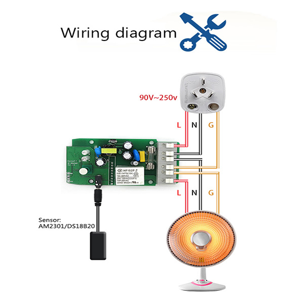
Sonoff Th16 Wiring Diagram

Rj11 Socket Wiring Diagram Australia, How to punch down an RJ11 Telephone Jack, 6.36 MB, 04:38, 387,634, CableSupply.com, 2009-08-05T00:16:...